|
PRS
CO2
CUT4000
Reactor |
| |
|
過去に無いSkimmerから入るエアーの
"CO2" Cut Reactor!
|
|
”CO2 吸着メディアでCO2を吸収” |
|
”Skimmerから入るエアーのCO2濃度をモニター表示” |
|
CO2 absorbent will absorb CO2 that going to Skimmer |
|
” KHの安定”・Phの安定 ・ コケの抑制 |
|
KH and Ph will become stable and control occurrence
of moss |
|
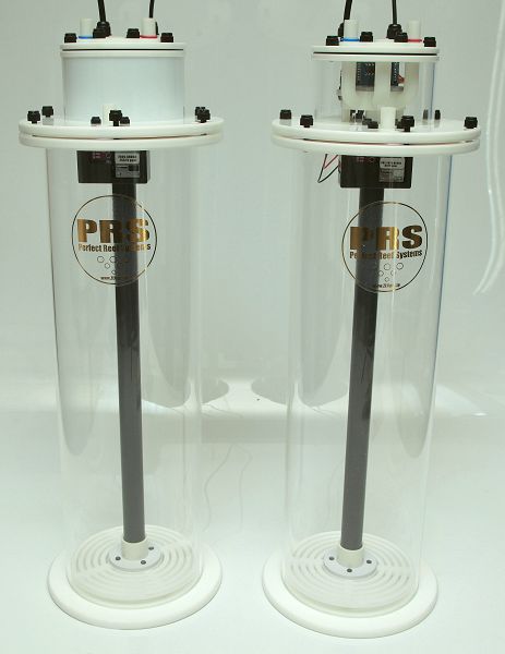
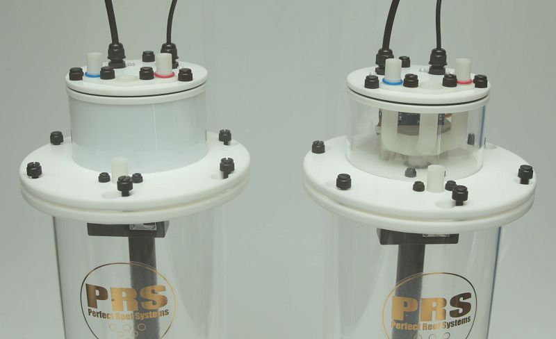
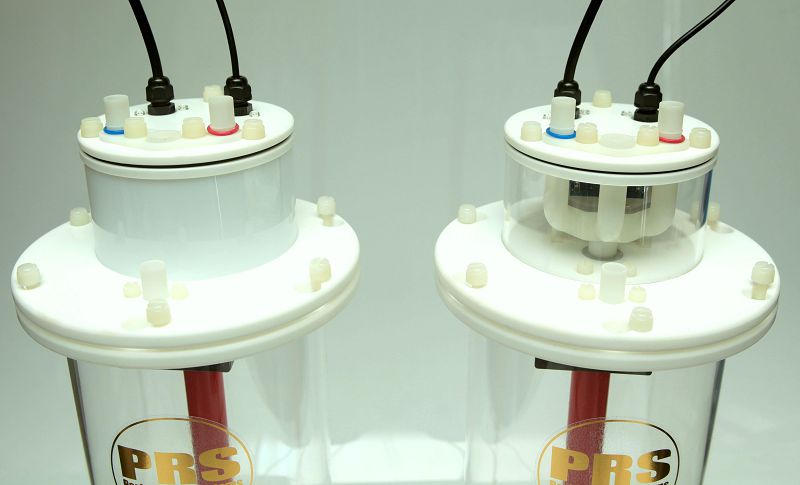
White Color White Clear |

Red
Color Red
Clear |
|
|
 |
|
|
|
|
|
CUT4000 Reactor |
|
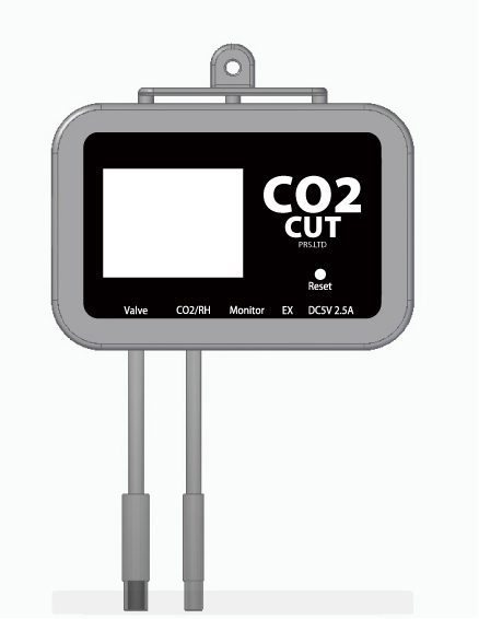
CO2 コントローラー |
|
CO2 Controller |
|
|
AC/DC アダプター 5V 2.5A 1ケ
|
| AC/DC Adapter 5V 2.5A |
| |
|
シリコンチューブ 2m
|
| Silicon Tube |
| |
|
チューブホルダー(アクリル/ガラス共用) 1ケ
|
| Tube Holder |
| |
|
CO2 CUTメディア 4L(別売り) |
| CO2 CUT Media(Option) |
|
|
CO2
CUT4000のセッティングの前に
Before Setting |
|
| |
|
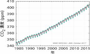
| ご存知の様に大気中のCO2濃度はおよそ400ppmである事が知られています。し |
| かし右図の様に30年ほど前は350ppm前後でした。最近の大気中のCO2は既に |
| 400ppmを超え世界平均は420ppm程と成っている様です。この事がどの様な問題 |
| を引き起こしているかはご存知の通りだと思います。 |
| |
| As you know, the
CO2 concentration in the atmosphere is known to be
about 400ppm.However, |
| as shown in the
figure on the right, it was around 350ppm about 30
years ago. It seems that the |
| recent
atmospheric CO2 has already exceeded 400ppm and the
world average is about 420ppm. |
| You know what
kind of problem this is causing. |
| |
| CO2濃度が夏に減少し冬には増加、日中は減少し夜間は増加します。これは主 |
| に、 植物が光合成や呼吸を介して大気と二酸化炭素のやり取りをする様相 |
| が 季節によって変化するためです。このようなやり取りは地表面付近で行われま |
| すが、大気の流れによる輸送によって上空の二酸化炭素濃度にも季節変動が反 |
| 映されます。この様にCO2濃度は、一定ではなく様々の状況下で常に変化してい |
| ます。 |
| |
| CO2 concentration
decreases in summer and increases in winter,
decreases during the day |
| and increases at
night. This is the main In addition, the appearance
of plants exchanging carbon |
| dioxide with the
atmosphere through photosynthesis and respiration. |
| Is because it
changes with the seasons. Such exchanges take place
near the surface of the |
| earth. However,
seasonal fluctuations are also reflected in the
concentration of carbon |
| dioxide in the
sky due to transportation by the flow of the
atmosphere. It will be projected. In
|
| this way, the CO2
concentration is not constant and is constantly
changing under various |
| circumstances. I
will. |
|
 |
|
|
|
|
|
|
|
|
アクアリウム飼育での海水では主にプロティンスキマー又は淡水ではエアレーションなどが多く使われています。これらの機器から常に永遠と420ppm以上のCO2を入 |
|
れ続けています。CO2センサーを室内に設置されている方はご存知とは思いますが、室内の場合は500〜1000ppm以上に成る事は常に有ります。
この様な |
| CO2をアクアリウムに入れ続ける事はPhの低下・酸化・コケの発生・イオンの分子化(KHの低下)などを早めます。よってCO2混入を減らす事でこれらの事の促進 |
| を押さえる事が目的です。 |
| |
| In seawater in
aquarium breeding, a protein skimmer or aeration is often used in
freshwater. Always forever and more than 420ppm CO2 from these
devices It continues to be. |
| As those who
have installed a CO2 sensor indoors know, it can always be 500 to
1000ppm or more in the case of indoors. Like this Continuing
to put CO2 in the aquarium |
| accelerates the
decrease in Ph, oxidation, generation of cocoa, and molecularization
of ions (decrease in KH). Therefore, promoting these things by
reducing CO2 contamination |
| The purpose is to
hold down. |
|
CO2
CUT4000セッティングの準備
Prepare setting |
|
|
|
|
|
|
|
| |
|
|
|
|
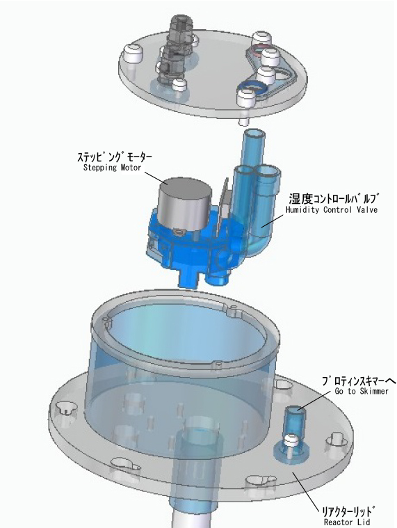
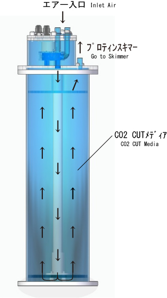
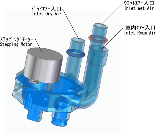
| プロティンスキマーから吸込まれる空気は、室内エアー入口・ウエットエアー入口・ドライエアー入 |
| 口のどちらかからリアクター内の湿度センサーによって適切な入口が判断され空気を吸 |
| い込みます(この件は後で詳しくご説明致します)。 |
| 吸込まれた空気はCO2 CUTメディアを通りCO2を吸着した後プロティンスキマーから排 |
| 出されます |
| |
| The air sucked
from the protein skimmer enters the indoor air
entrance, the water air entrance,
|
| and the driver.
The humidity sensor in the reactor determines the
appropriate inlet from either |
| of the mouths and
sucks air. I will enter (I will explain this in
detail later). |
| The sucked air
passes through the CO2 CUT media, adsorbs CO2, and
then is discharged from the |
| protein skimmer.
Will be issued |
| |
|
|
| |
|
|
|
|
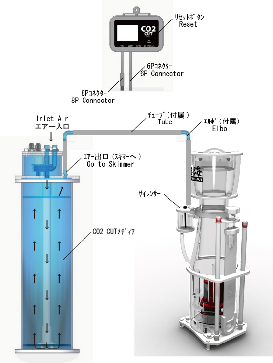
CO2
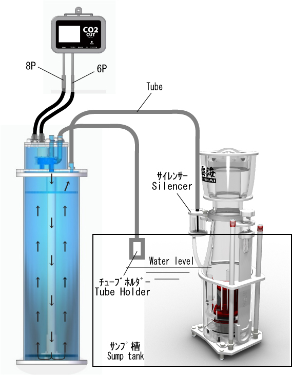
CUTリアクターにメディアを入れリアクターのエアー出口とスキマーのサイレンサーを付属チューブで接続します
|
| |
|
Put the media in the CO2 CUT
Reactor and connect the air outlet of the
Reactor and the silencer of the skimmer with
the attached tube. |
|
|
|
|
湿度コントロールバルブ
Humidity Control Valve |
|
|
|
|
湿度コントロールバルブ |
|
Humidity Control
Valve |
|
湿度コントロールバルブの必要性 |
| 一般にCO2を吸着する メディア (以下CO2 CUT)はCO2を吸着する為にある |
| 一定範囲の水分量が不可欠となります。つまり、この水分が無いとCO2
CUT |
|
はCO2を吸着する事ができません。この種の吸着材は数種類有りますが、全 |
| て同様な性質を持ちます。 CO2
CUT自身で有る程度の水分量は当初か ら保 |
| 持しているのですが、 入ってくる空気の乾燥度により
直ぐメディア内の水分が無 |
| くなり、湿度の低い時期・地域では殆ど全く働かなくなります。 |
| 当社のテストでは大よそ11月前後〜3月前後(関東地方)でCO2の吸着能力
が |
| 安定しなくなり吸着能力が低下し、まったく吸収しなくなることが分かっています |
| よって、 CO2を安定して吸着させる為には、メディア内に入る空気の
湿度をコントロ |
| ールする必要が有ります。 |
| PRSのCO2 CUTリアクターは湿度コントロールバルブを使用する事で安定したCO2の |
| 吸着を継続します。 |
| |
| CO2
CUTの能力はおよそ1ヶ月/1L(10Lエアー/毎分供給時)CO2 CUT4000 |
|
は最大4L入るので、およそ4ヶ月間持続します。勿論室内のCO2レベルにより |
|
その範囲は前後致します。 |
| |
| CO2 adsorption media
requires an appropriate amount of water to adsorb CO2. The
media will not |
| work without this
moisture. Humidity control valve controls the humidity
entering the CO2 CUT |
| reactor |
|
Period of
use : 1 month/1L(10L Air/min) |
|
|
|
|
|
|
 |
|
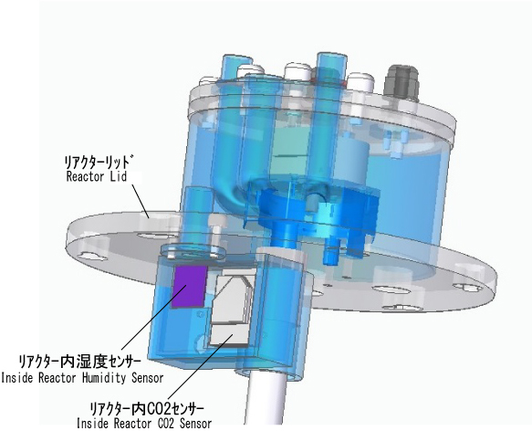
リアクター内CO2センサー/湿度センサー |
|
リアクターリッド(フタ)を取外すとその下にCO2センサーと湿度センサーが取付けて有りま |
| す。この2つのセンサーはリアクター内のCO2(ppm)と湿度(RH%)を測定します。 |
| |
|
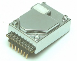
CO2(ppm) |
| 現在市販されているCO2センサーはほとんどが400ppm以下の測定ができません |
| (必要性が無い為)しかしPRSのCO2センサーは400ppm以下を測定できる様にプロ |
| グラムを変更して使用しています。 |
|
CO2センサーの測定誤差はどのセンサーも凡そ±50ppm有ります |
| |
|
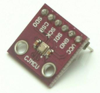
相対湿度(RH%) |
| 現在市販されている湿度計は相対湿度計(RH%)です。相対湿度を下表からご |
| 説明させて頂くと、たとえば ”温度が20℃/相対湿度が88%”の室内が有るとします温度20℃の時の空気中に存在出来る蒸気量(水分量)は最大で17.2g/m3です。つまり
相対湿度が88%ですので、 およその室内には15g/m3程の蒸気量が存在しています。そこでこの室内の温度を10℃にすると表から分かるように10℃の時の空気
中に存在出来る最大蒸気量は9.3g/m3ですので、15g/m3-9.3g/m3=5.7g/m |
| 分の蒸気量がガラス面などに露結し相対湿度が100%になります。つまり相対湿 |
| 度とは同じ室内でも温度によって違うと言う事です。逆に室内を30℃にすると |
| 表から分かるように相対湿度は50%と成ります。 |
|
相対湿度(%) :
空気中に含むことができる最大の水蒸気量に対して、現在の水蒸気量は |
|
どれくらいかを表したものを言います |
|
絶対湿度(g/m3) :
空気1m3中に何gの水蒸気が入っているかを表した物です |
| |
| PRSのCO2 CUTリアクターは温度と湿度の関係からどの温度においても一定の条 |
| 件でCO2 CUTメディアを安定して動作出来る様マイコンで動作させています。 |
|
|
|
|
|
|
|
|
|
|
|
|
|
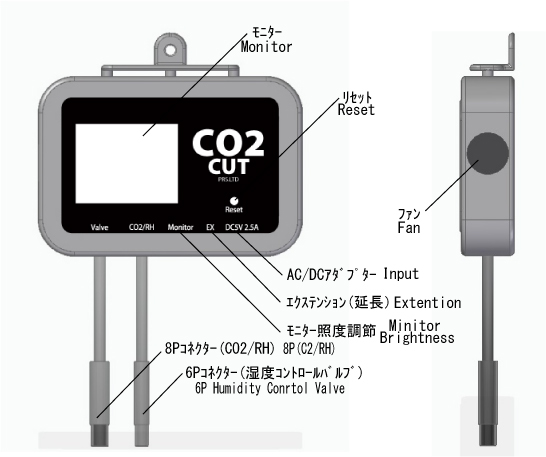
エクステンション(延長)
Extention |
| CO2コントローラーの下部にマイクロUSBポートが有ります。これは現状では |
| 使用する事が出来ません。 将来バージョンアップの可能性の時期の為の |
| ポートです。(バージョンアップの際は再度PRSからご連絡いたします) |
|
Version upgrade for the future |
| |
|
CO2コントロラー内のCO2センサー/湿度センサー (オプション) |
|
※CO2コントローラー内には室内測定用のCO2センサー/湿度センサーは含まれていません |
|
Inside Controller
CO2 Sensor and Humidity Sensor for Room (Option) |
|
|
|
 |
|
|
|
|
|
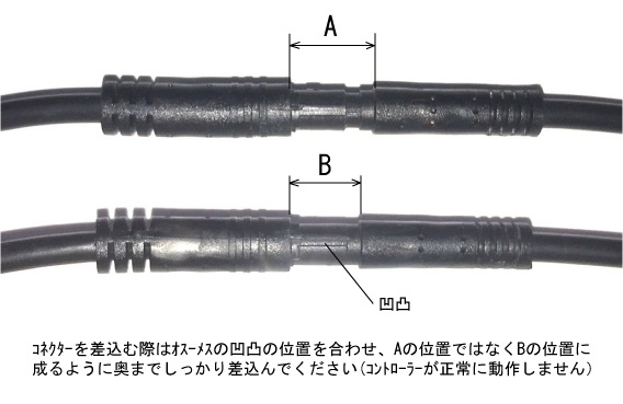
※8ピンコネクターは差し込みがキツイのでしっかり奥まで差し込んでください |
|
Insert the connector
to the B position instead of the A position (the
controller does not work properly) |
|
|
|
|
|
|
|
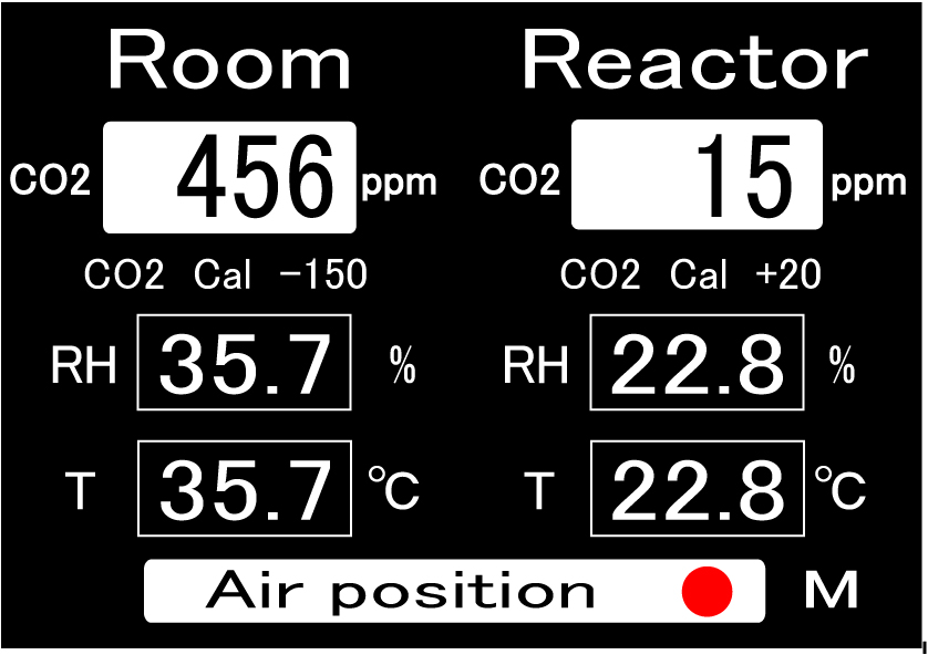
CO2コントローラー内に室内測定用のCO2センサー/湿度センサーを追加する事が出来ます。追加した場合は右側のモニター表示に変更されます |
|
CO2 sensor
/ humidity sensor for indoor measurement can be added to the
CO2 controller. If you add it, it will be changed to the
monitor display on the right side. |
| |
オプション(必要な場合は予めご注文ください) |
|
If you want to know
CO2 / humidity level of
indoor measurement ,please ask to us that beforehand
(Option) |
|
|
|
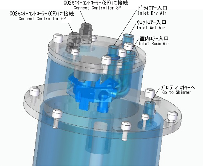
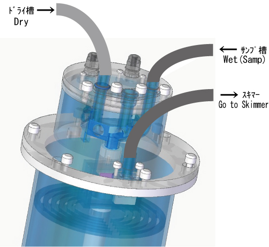
●ウエットエアー入口
●室内エアー入口
●ドライエアー入口 |
|
●Wet
Air
●Room Air
●Dry Air |
|
|
|
リアクター (
CO2センサー/湿度センサー)表示
|
|
| |
|
コントローラー内の室内(Room)CO2センサー/湿度センサー取付は |
|
下記に示す取付方法を参照 |
| |
| |
| |
|
室内(Room)とリアクター (
CO2センサー/湿度センサー)表示
|
|
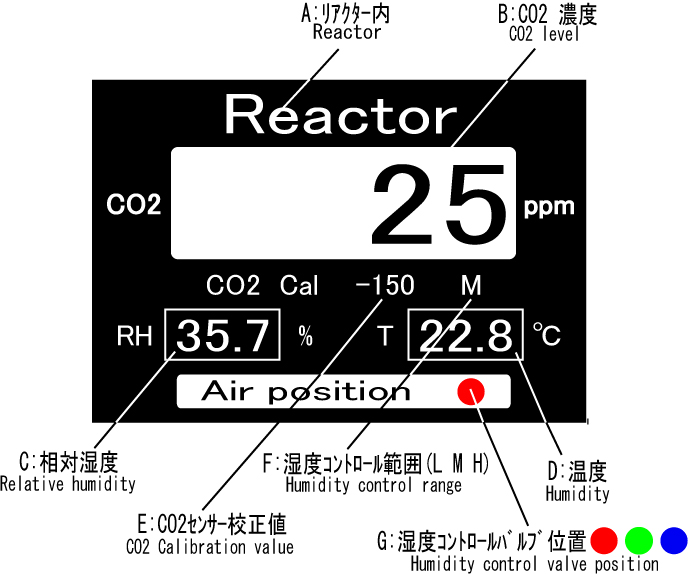
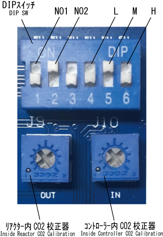
| A : リアクター内表示 Inside
Reactor |
| B : リアクター内CO2濃度 Inside
Reactor CO2 level |
| C : リアクター内相対湿度 Inside
Reactor Relative humidity level |
| D : リアクター内温度(30分後程で適正値になります)
Inside Reactor Temperature |
| E : CO2センサー校正値(PRSの基準とするCO2センサーとの差。-150の意味は基準とするCO2センサーより150高く表示されるので-150で調整) |
| CO2
calibration value (Calibration
value at reference CO2) |
| F : 湿度コントロール範囲(PRSで設定したリアクター内の湿度範囲で湿度コントロールバルブが動作 L-低い範囲 M-中間範囲 H-高い範囲) |
| 出荷時設定:M (DIPスイッチ) |
|
Operating humidity range of humidity control valve
set by PRS. At the time of
shipment set M |
G : 湿度コントロールバルブのエアーを吸込んでいる位置( ) ) |
|
|
モニター
ERR表示
|
| A : DIPスイッチ
ERR |
| 湿度コントロール範囲は出荷時"M"
だけがONに成っていますが、2つ以上又はL・M・Hの全てがOFFの場合ERR表示。必ず1つだけONにし |
| てください。その後リセットを1回押す |
|
The humidity control range is set to ON only for "M"
at the time of shipment, but ERR is displayed when
two or more or all of L, M,and H are OFF. Be sure to
turn on only |
|
one please. Then press reset once |
| |
| B : I2C device 0 ERR |
| I2Cとは湿度センサーの事をで "I2C device 1"はリアクター内に湿度センサーがある事を意味します。"I2C
device 2"はリアクター内とコントローラー内 |
| に湿度センサーがある事を意味します。"I2C device 0
ERR"は湿度センサーが無いか破損している事を意味します |
|
I2C means a humidity sensor, and "I2C device 1"
means that there is a humidity sensor in the
reactor. "I2C device 2" is in the reactor and
controller .It means that there is |
|
a humidity sensor in. "I2C device 0 ERR" means that
the humidity sensor is missing or damaged. |
| |
| C : Switch ERR |
| モーターの回転位置制御スイッチの異常時に表示します |
|
Displayed when the motor rotation position control
switch is abnormal |
| |
| D : Motor ERR |
| モーターの異常時に表示します |
|
Displayed when the motor is abnormal |
| |
|
異常CO2値表示
|
|
CO2センサーは非常に精密でデリケートなセンサーです。落下・衝撃等で大きくCO2表示が変化・故障する事が有ります。CO2センサーの保証は有りません |
|
のでメディアを交換する際CO2センサー部分のパーツを十分に注意して取扱ってください。また、コントローラー内にCO2センサーを取付けて有る時は、コントローラー |
| を固定し落下・衝撃等に十分注意してください |
|
The CO2 sensor is a very precise and delicate
sensor. The CO2 display may change or malfunction
due to dropping or impact. There is no guarantee of
CO2 sensor. Therefore, |
|
when replacing the media, handle the parts of the
CO2 sensor with great care. Also, if a CO2 sensor is
installed in the controller, the controller. Please
be careful not to drop or |
|
impact. |
|
|
|
|
コントローラー内への室内(Room)CO2センサー/湿度センサーの取付方法(室内のCO2 ppmと湿度 %を測定) |
|
|
How to install the room
CO2 sensor / humidity sensor in the controller (measure
the CO2 ppm and humidity% in the room) |
|
| 1 |
How to install the room CO2
sensor / humidity sensor in the controller (measure the CO2
ppm and humidity% in the room)
|
電源を外す |
AC/DCアダプターの電源を外す
Remove the power
supply of the AC / DC adapter |
|
| 2 |
|
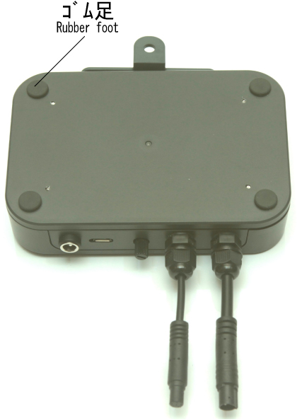
A : コントローラーの背面パネルに有る4ヶのゴム足を外す
A: Remove the 4
rubber feet on the back panel of the controller. |
|
B : ゴム足の中にある4ヶの取付ネジを外す
B: Remove the 4
mounting screws in the rubber feet |
|
※6ピンコネクター/8ピンコネクターは外す必要はありません
It is
not necessary to remove 6 pin /8 pin connector.
|
|
|
|
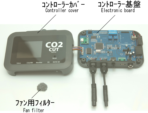
A : コントローラーカバーの右側にあるファン用フィルターを取外す
A: Remove the fan
filter on the right side of the controller cover. |
|
B : コントローラーカバーとコントローラー基盤を写真の様な位置にセット
B: Set the controller
cover and controller board in the position shown in
the photo. |
|
| 3 |
|
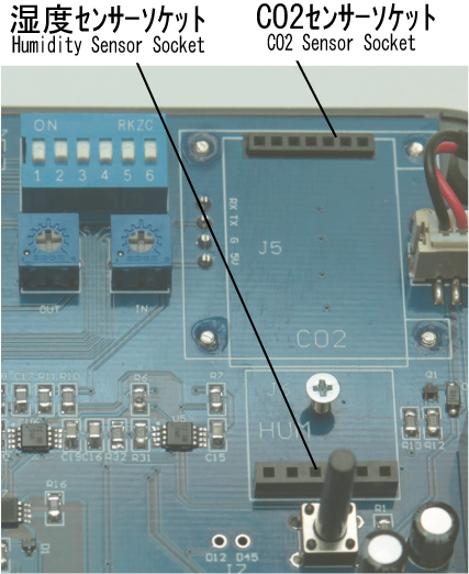
コントローラー内へCO2センサー/湿度センサーの取付 |
|
|
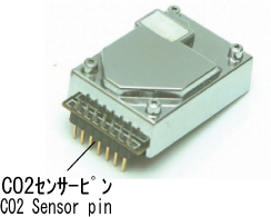
CO2センサー |
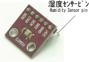
湿度センサー |
|
|
| A :
CO2センサーの裏側にある両面テープを剥がし写真の向きにCO2センサーをCO2センサーソケットに差込む。その際CO2センサーと基盤がしっかり固定されている事 |
| を確認する |
| A: Peel off the
double-sided tape on the back side of the CO2 sensor
and insert the CO2 sensor into the CO2 sensor socket
in the direction shown in the photo. At that
|
|
time, the CO2 sensor and the base are firmly fixed
Check |
| B :
湿度センサーの裏側に有る両面テープを剥がし写真の向きに湿度センサーを湿度センサーソケットに差込む。その際湿度センサーと基盤がしっかり固定されてい
る事 |
| を確認する |
| B: Peel off the
double-sided tape on the back side of the humidity
sensor and insert the humidity sensor into the
humidity sensor socket in the direction shown in the
|
|
photo. At that time, the humidity sensor and the
base must be firmly fixed Check |
| |
| 注 :
それぞれのセンサーをソケットに差込む際、ソケットとセンサーピンの位置を良く確認し差込んでください。ずれた位置に差込み電源を入れるとセンサーが破損します |
|
Note : When inserting
each sensor into the socket. check the position of
the socked and the sensor carefully before inserting
. If you plug it in the wrong position and |
|
turn on the power,
the sensor will be damageed . |
|
| 4 |
|
DIPスイッチ NO2 をON |
|
|
DIPスイッチ NO1をOFF(下側)にしてNO2をON(上側)にする。コントローラー(室内)とリアクター (
CO2センサー/湿度センサー)表示モード |
|
Turn DIP switch NO1
OFF (lower side) and NO2 ON (upper side). Controller
(indoor) and reactor (CO2 sensor / humidity sensor)
display mode |
|
| 5 |
|
モニター表示の確認 |
|
|
以上のセットが終了したら、コントローラーにAC/DCアダプターを取付電源をいれる。モニター表示が2台のCO2,湿度センサー表示に成ったことを確認 |
|
この時点では、コントローラー内のCO2センサーはまだ校正されていません |
| After
completing the above sets, attach the AC / DC
adapter to the controller and turn on the power.
Confirm that the monitor display is now the CO2 and
humidity sensor |
| display
for the two units. At this point, the CO2 sensor
in the controller has not yet been calibrated. |
|
| 6 |
| A : 基盤内のDIPスイッチNo1をONにする(校正数字が点滅する) |
|
A: Turn on the DIP switch No. 1 in
the board (calibration number blinks) |
| B : 右側のコントローラーCO2校正器(IN)の校正ダイヤルを回しモニター表示のRoom |
| 側のCO2 Cal数字をCO2センサーに表示されている値に成る様に調整す
る |
| B: Turn the
calibration dial of the controller CO2 calibrator
(IN) on the right side and adjust |
|
the CO2
Cal number on the Room side of the monitor display
so that it becomes the |
|
value displayed on the CO2 sensor. |
| C : 校正が終了したらDIPスイッチNo1をOFFにする(校正終了) |
|
When the calibration is completed,
turn off the DIP switch No. 1 (calibration
completed) |
| |
| ※リアクター内CO2は出荷時に校正済です |
|
|
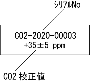
それぞれのCO2センサーには上に示す様なラベルが貼られています |
|
上-シリアルNo、下-校正値(基準値とする他のCO2センサーとの校正 |
|
値) |
|
Each CO2 sensor has a
label as shown above. Top-serial number, bottom- |
|
calibration value
(calibration with other CO2 sensor as reference
value) |
|
|
|
+35±5 ppm とは、このセンサーは基準となるCO2センサーと |
| +35ppmずれていると言う意味です |
| +35
± 5 ppm is the standard CO2 sensor Difference |
|
| 7 |
|
コントローラパネルを元に戻し、4ヶの取付ネジで固定し、ゴム足ゴム足を取付け、ファン用フィルターをセットして終了 |
| Replace the
controller panel, fix it with 4 mounting screws,
attach the rubber feet, set the fan filter, and
finish. |
| 注 :
コントローラーパネルを戻す際、モニターコード・リセットボタンの穴位置等に注意し取付けてください |
|
Note: When returning the controller panel, pay
attention to the hole positions of the monitor code
and reset button |
|
|
| 8 |
| コントローラーのファンの箇所からゆっくりと2〜3回息を吹きかけて見てください。Room
CO2レベルが大きく変化する事が確認できます |
| Breathe slowly
from the fan of the controller a couple of times.
You can see that the Room CO2 level changes
significantly. |
| 注 :
安定した正確なCO2値はおよそ1h後からを参考にしてください |
|
Note: Please refer to after about 1h for stable and
accurate CO2 value. |
|
|
|
|
CO2
CUT4000セッティング
Setting |
|
|
|
|
 |
| PRSの関東地方での通年におけるテストでは、ドライ槽等に接続 |
|
る事は有りませんでした。使用環境に応じ対応してください |
| (リアクターの下部から水滴が落ちる様な湿度が高い時)また、湿 |
| 度コントロールバルブが室内エアー●Roomから吸込む時期・地域では |
| サンプ槽との接続を外しても結構です |
|
|
|
|
セッティング
|
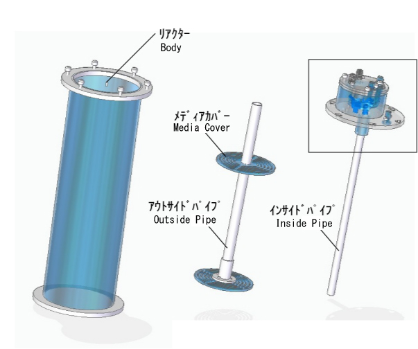
1.リアクターをCO2
CUT4000分解図の様に3種類のパーツに分ける CO2
CUT4000分解図へ |
| |
2.メディアカバーを引き抜きアウトサイドパイプをリアクターにセットする |
| |
3.リアクターにメディアをセットする(MAX4L)
注:メディアを入れる際メディアがアウトサイドパイプ内に入らない様注意してください |
| |
4.インサイドパイプをアウトサイドパイプの内側に差込む |
| |
5.コントローラーからのコード(6Pと8P)をそれぞれCO2
コントロールバルブ8Pとリアクター6Pのコネクターに接続 |
| |
6.リアクターのエアー出口からスキマーへ付属チューブを使用しスキマーのサイレンサーに接続 |
| |
7.サンプ槽に付属チューブホルダーを取付、ウエットエアー入口に付属チューブを使用して接続 |
| |
8.AC/DCアダプターをコンセントに差込み、モニターがリアクター又はリアクター+Roomの表示されたことを確認
モニター表示 |
| |
注:モニターが正常に表示されない場合はリセットボタンを一度押す |
| |
9.スキマーを稼働させる |
| |
|
| |
A:メディア交換時はコントローラーのAC/DCアダプターのコンセントを抜き1〜9を再度行う |
| |
|
|
|
依頼 :
この商品は予告無に変更する事が有ります(ハード面/ソフト面)。その際は前もってPRSからこのHP上でご連絡致 |
|
します。ソフト面での変更が発生した場合は、HP上でバージョンアップ・ダウンロードが個々に出来る様に準備をする予定 |
|
です。個々でのバージョ ンアップ・ダウンロードが難しい場合はPRSまでお送りください。 |
|
|
|
ハード面での変更が有った場合は交換可能な個所のみの交換で対応させて頂きます。その際の費用は別途とさせ |
|
て頂きます |
|
(往復の送料はお客様のご負担でお願い致します) |